
vaka-calismasi
February 28, 2020
Norm Cement – Baku Multi-Chamber Silo & Facilities
Read article→
A 252-metre reinforced concrete chimney with twin steel flues in Zonguldak — a turnkey industrial structure examined through its design basis, tapered slipform method and on-site execution.
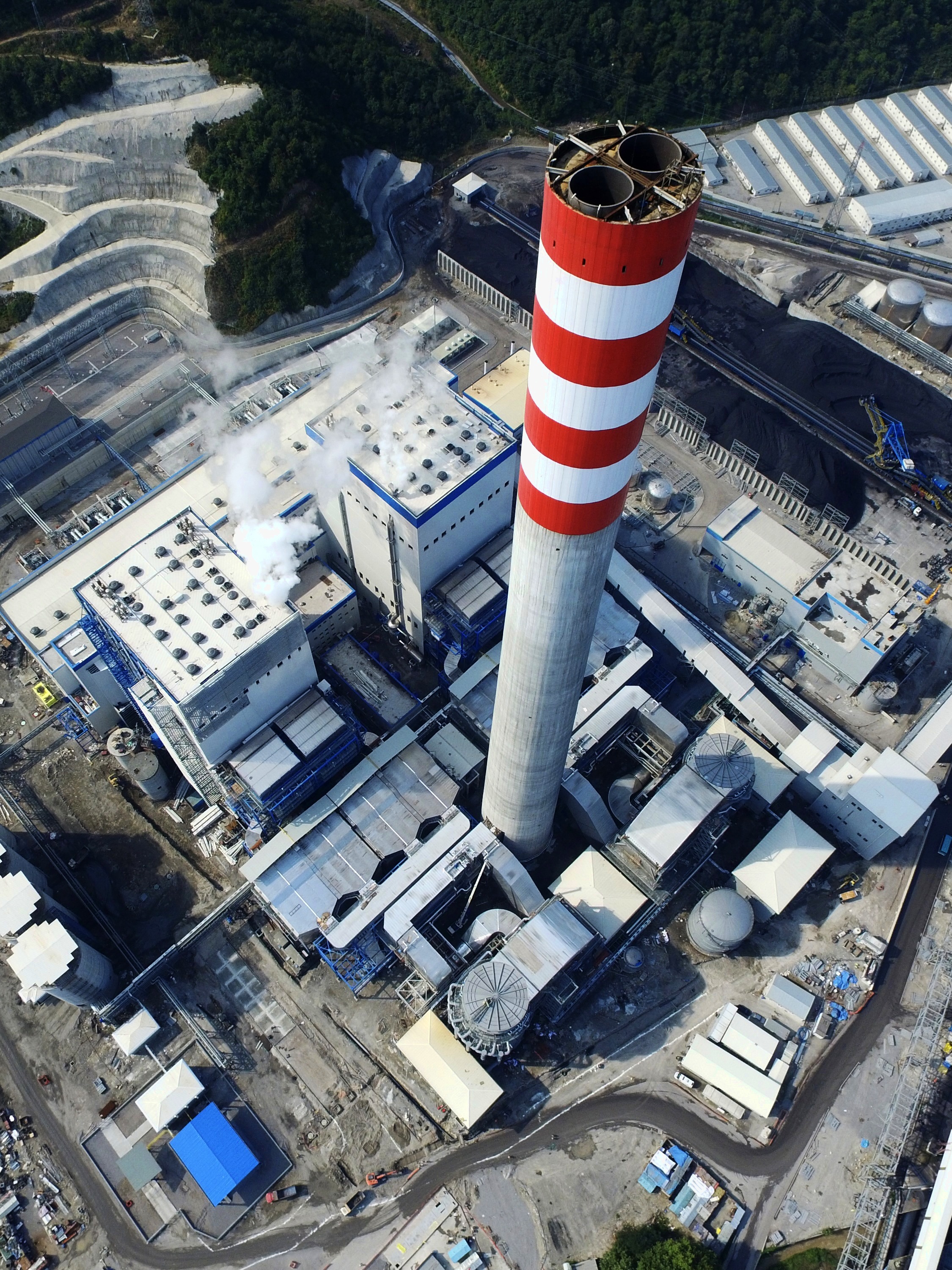
ZETES III Thermal Power Plant is a large-scale energy investment located in Zonguldak, Turkey. Under this project, SİBA delivered the 252-metre reinforced concrete chimney with twin steel flues on a turnkey basis — design, engineering, fabrication and erection. This case study brings together the engineering context, the design basis and the on-site construction methods of the structure.
At 252 metres, the structure is the tallest twin-flue chimney in Turkey and one of the limited number of chimneys exceeding 250 metres worldwide. Industrial chimneys of this scale belong to a class of slender shell structures whose behaviour departs from conventional building engineering. For this class, dynamic and environmental actions — rather than static loads — govern the response, so the design requires an integrated assessment of aerodynamic, thermal and seismic effects.
For structures of this class, wind is the governing action. Wind effects are examined in two components: along-wind drag forces and across-wind oscillations induced by vortex shedding. Because vortex-induced vibration can be decisive for fatigue in slender chimneys, the natural frequencies and damping behaviour of the structure are an integral part of the design. Self-weight, seismic actions and the thermal stresses arising from the temperature difference between the flue gas and the ambient environment are considered alongside these.
A 252-metre chimney is not merely tall; it is an integrated engineering system that must remain safe for its entire service life under wind, thermal and seismic actions.
The structure is built on a principle that separates two functions: the outer tapered reinforced concrete shell performs the load-bearing role, while the two internal steel flues carry the flue gas. This separation prevents the hot and chemically aggressive flue gas from acting directly on the concrete shell, allows the steel flues to expand independently of the shell, and provides — through the annular space between flues and shell — access for inspection and maintenance.
The upward-tapering conical section is a deliberate engineering choice. The section is widest at the base (24.4 m), where the bending moment is greatest, and narrower at the upper levels (19.1 m), where the moment decreases, so that material is placed in accordance with the distribution of internal forces. This geometry reduces both the wind load and the self-weight at height while efficiently providing the stiffness required against the overturning moment.
The chimney shaft was built using approximately 33,000 m² of tapered slipform. The slipform method produces a jointless, monolithic shaft by continuously jacking the form upward. In a conical shaft the diameter of the form must be reduced progressively with height, which requires simultaneous and precise control of the concrete setting rate, the form-jacking speed and the section geometry. Continuous placement secured both structural continuity and construction speed.
Over a 252-metre shaft, verticality is the most critical aspect of tolerance management. Continuous surveying and feedback are applied throughout the advance of the slipform to limit axis deviation, and the smallest deviations are corrected at an early stage. The section geometry was controlled along the full height through disciplined on-site surveying and execution management.
The twin steel flues inside the structure were fabricated on site. More than 1,300 tons of steel were fabricated in a temporary workshop set up on site and protected against corrosion by sandblasting and painting. The heavy lifting operations were carried out using strand jack systems, which allow synchronised and controlled lifting.
In tall industrial structures, durability and safety are integral to the design. The steel flues that carry the flue gas are selected against thermal and chemical action, while the concrete shell is designed with a durable-concrete approach aimed at a long service life. The structure is marked with aviation warning paint and warning lighting in accordance with aviation regulations and is equipped with the lightning protection systems required for tall structures.
ZETES III is a concrete example of an engineering approach able to manage the entire process — from design to erection — under a single roof. By combining slender reinforced concrete shell design, tapered slipform construction, large-scale steel fabrication and heavy lifting within a single turnkey scope, the project stands among SİBA's heavy-industrial-scale references.